Welcome to the Datatron 205 and 220 Blog

This blog is a companion to T J Sawyer's Web Page that outlines the history of the Burroughs Datatron 205 and Paul Kimpel's incredible 205 and 220 emulators. Please visit those sites and return here to post any comments.

Sunday, July 29, 2018

Algol-58 – The International Algebraic Language

By the early 1950s, the number and variety of electronic computers were increasing, the scope of their application to science, business, and government was rapidly expanding, and the demand for the programming those applications required was expanding in concert. This demand stimulated the need for increasingly efficient and effective ways to prepare programs, which in turn led to the development of higher-level programming languages.

One of the first attempts at designing a universal programming language, at least for numeric computation, was the International Algebraic Language (IAL), also known as Algol-58. The Burroughs Algebraic Compiler (BALGOL) for the 220 computer system was an early dialect of Algol-58. To prepare for a detailed discussion of BALGOL on the 220 in the next post [1], this post will discuss the development of Algol-58 and present an overview of the language.

Background


Initially, preparation of the program steps for machine execution was done entirely on the machine's terms. Instructions were prepared directly using the numeric or alphanumeric code required by the hardware. Hence the popular use of "code" and "coding" as synonyms for programs and programming. There is a lot of manual bookkeeping involved in programming at this level, especially in keeping track of addresses within the code for data storage and branch locations. That bookkeeping task is compounded when changes must be made to an existing program.

Mnemonic notations arose fairly quickly to ease the clerical task of coding, along with a number of higher-level abstractions, such as flowcharting, to aid in the overall conception and design of programs. Not long after, people began to realize that the machine itself could assist with the clerical aspects of generating code, especially in keeping track of address assignments. This led to the development of assembly languages and the assembler programs to process them.

From the very beginning of automated computing, though, there has been a strong desire to be able to approach programming more on our terms, in a way that is more in keeping with the way we think about the applications to which we want to apply a computer. Since most early applications involved numerical calculations based on mathematical formulae, there was an obvious desire to express programs using standard notations from mathematics. FORTRAN is one of the earliest and best known realizations of this desire, but as Donald Knuth made clear in his 2003 lecture, "A Dozen Precursors of FORTRAN" [2], attempts to express programs using higher-level abstractions can be traced all the way back to Konrad Zuse during the 1940s.

A parallel desire has been to be able to express programs in a more general way than in the coding for a specific type of machine. The half-life of a given computer design in the 1950s was only a couple of years, so as new designs came along, existing programs had to be completely redone using the instruction coding for each new machine. Being able to express programs in a way that was not specific to any particular machine would ease this burden. It would also open the possibility of more easily adapting programs written for one machine so that they could run on entirely different ones.

Many efforts towards translation of standard arithmetic expressions into machine instructions were going on, starting in the early 1950s. A preliminary report on FORTRAN was available by 1954, but other languages were starting to appear, such as Alick Glennie's Autocode, Alan Perlis' Internal Translator (IT, also known as the Purdue Compiler), and Grace Hopper's A0 and MATH-MATIC. There were also a number of interpretive expression evaluators, such as the Whirlwind Algebraic Interpreter. By the second half of the 1950s, the number of different (and incompatible) programming notations was beginning to proliferate.

In 1955, the German Association for Applied Mathematics and Mechanics (GAMM) held a meeting in Darmstadt on electronic computers. This resulted in the formation of a committee to work on formula translation. Then in May 1957, the Association for Computing Machinery (ACM), SHARE (the IBM user organization), USE (the Sperry Univac user organization), and DUO (the ElectroData/Burroughs user organization) held a conference in Los Angeles to explore the exchange of computing information. The group concluded that a single, universal programming language would be very desirable, and recommended that the ACM form a committee to pursue the idea. A few months later, the GAMM group reached a similar conclusion and contacted the ACM to suggest a joint conference that would make recommendations on a common language.

By April 1958, both the ACM and GAMM committees had independently developed proposals for a universal language and met to exchange them. They found they had much in common, so arranged to hold a joint working session between representatives of each group to combine their proposals and resolve the differences. That joint session was charged with the following objectives [3]:
  1. The new language should be as close as possible to standard mathematical notation and be readable with little further explanation.
  2. It should be possible to use it for the description of computing processes in publications.
  3. The language should be translatable into machine programs.
The joint ACM-GAMM meeting was held in May 1958 at ETH in Zurich, Switzerland. The product of that meeting was the "Preliminary Report—International Algebraic Language" [3]. The language was initially referred to as the IAL, but the name was soon determined to be unsuitable, and Algol, short for "algorithic language," was suggested instead. The successor to the preliminary IAL was known as Algol from the start, so to distinguish them, the IAL eventually became known as Algol-58 and its successor as Algol-60.

FORTRAN had been released by IBM for almost a year by the time of the 1958 ACM-GAMM joint session in Zurich. FORTRAN was being received warmly, especially by the scientific community. It was not exactly an attractive notation, though, and was certainly not an ideal way to exchange definitions of algorithmic processes, especially among people accustomed to the elegance of mathematics. Even John Backus, the driving force behind FORTRAN, could not have been completely pleased with it, as he was one of the ACM representatives to the Zurich joint session. Thus, there was motivation to come up with something much better.

Overview of Algol-58


This section attempts to describe the IAL as presented in the Preliminary Report in somewhat informal terms. It largely follows the structure of that Report.

Symbology

 
Algol-58 uses a 63-character set, which allowed for a number of traditional mathematical symbols, and may have been influenced by six-bit codes for teletype and punched paper-tape equipment. Early FORTRAN, of course, had been limited by the 48-character set used in IBM punched-card equipment.

The basic symbols defined for the language are:
  • The 26 English letters: A-Z [including both upper and lower case; the report is silent on the subject of case sensitivity]
  • The decimal digits: 0-9
  • Arithmetic operators: +     ×   /
  • Relational operators: <      =      >  
  • Logical operators: ¬ [not]   [or]   [and]   [equivalence]
  • Sequential operators: go to,   do,   return,   stop,   for,   if,   or,   if either,   or if
  • Separators: .   ,   :   ;   :=   =:      10   begin   end
  • Brackets: (   )   [   ]     
  • Declarators: procedure,   array,   switch,   type,   comment
The role of spaces is not described in the Preliminary Report. It seems likely the intent is that, as in FORTRAN, spaces can be inserted for readability, but they do not serve as delimiters, and their presence or absence does not affect the interpretation of the program text.

Note that, as with Algol-60, the boldface words in the lists above are considered not to be identifiers or sequences of characters, but atomic symbols in their own right. Thus, "go to" is not two words or five characters, but a unique symbol in the language. The subscripted "10" is used to indicate the power-of-10 scaling factor for numbers in scientific notation.

Also note that this is the symbol set for the reference language, which is intended to specify the language itself and not necessarily be used for coding programs or publishing algorithms. The report anticipated that a more restricted set of characters, a hardware representation, would need to be used by an actual compiler targeting a real machine. It also anticipated that an expanded set of characters might be used in a publication language used to communicate algorithms in the literature. Each instance of a publication language or hardware representation is to be accompanied by a set of transliteration rules for mapping to and from the reference language.

Data Types and Declarations


The Algol-58 report specifies three data types – integer, real (floating-point), and Boolean (logical) values, plus arrays of these entities. It appears to anticipate the use of additional types, but is silent on how they should be handled.

Literals


Numeric literals have the general form I.F10±E, where I is a whole integer, .F is a decimal fraction, and 10±E is a scaling factor as a power of ten. The fraction and scale factor are optional, as is the sign preceding the exponent of the scaling factor. A number could also be expressed as simply a scaling factor by omitting the integer 1 before it, e.g., "10-3" for 0.001.

Boolean literals are represented as the integer literals 0 [false] and 1 [true].

Identifiers and and Types


Identifiers are defined in the usual way, starting with a letter and optionally followed by a string of letters and decimal digits. No maximum length for an identifier is specified.

By default, all identifiers are considered to refer to variables of type real. A type declaration can be used to specify that an identifier refers to an integer or Boolean variable. Note that the type declaration does not define a variable or assign it storage. The declaration merely associates a type with an identifier. Variables are declared upon first reference to their identifiers, which need not appear in any type declaration.
integer (i, j, k); Boolean (on, off);

Array Declarations


Array declarations name a list of identifiers to be considered as arrays and to specify the bounds of each array's dimensions. The bounds notation is a little different from Algol-60 -- all of the lower bounds are specified first in a comma-delimited list, then a colon (:), then the corresponding upper bounds are specified in a second comma-delimited list. The Report specifies the bounds to be "integers," so it appears that dynamic array sizing is not supported. Multiple array identifiers can be associated with a common set of bounds, as in Algol-60. If an array is to be of a type other than real, it must appear in a type declaration, and must be followed by square brackets containing sufficient commas to indicate the dimensionality of the array:
integer i, j, m[], n[,,];
array a, b, c[1:10], d[0, 0:7,19], m[-7:7], n[1,1:9,9];

Switch Declarations


A switch defines a multi-way branch, after the idea of the computed go-to in FORTRAN, but essentially the same as switches in Algol-60. Note that it is a declaration, not a statement. It defines an ordinal list of designational expressions, which are either simple statement labels or indexed switch identifiers. A statement label may be an identifier or a literal integer.

A switch is used by the go to statement, which takes as its target not a label, but the more general designational expression construct. The index used with a switch identifier is evaluated dynamically, not only for a switch named in a go to statement, but also for any switch identifiers used in designational expressions within switch declarations. Thus the evaluation of a designational expression may result in a cascade of switches being evaluated before a label is finally encountered and the destination of a branch determined.
switch s1:= (start, 44, s2[i×j-1], s1[k]);
switch s2:= (5, 4, 3, 2, 1, blastoff);

go to s1[3];

Comment Declarations


Algol-58 considers a comment to be a declaration. It can appear between any instance of other declarations and statements, but otherwise has no effect on the meaning of the program. Like the Algol-60 comment, it starts with the symbol comment and continues until the next semicolon (;) is encountered.

Function Declarations


Algol-58 supports the declaration of an expression as a function, similar to the in-line function of FORTRAN. The function defines a list of parameters, the actual values of which will be substituted into the expression. Any variables in the expression not named in the parameter list are referenced globally in the containing program.

toRads(degrees) := degrees×3.1415926/180;
Pythagorean(a, b) := sqrt(a↑2↓ + b↑2↓);

length := Pythagorean(base, height);
The language also supports procedure declarations and calls. These are a more complex subject, and are discussed in a separate section below.

Expressions


Expressions in Algol-58 are formed in the usual way, from combinations of variable references, function calls, and operators of various types. The values of scalar variables are referenced as simple identifiers. Elements of arrays are referenced as the identifier for the array, followed by a comma-delimited list of subscripts in square brackets ([ ]). Subscripts can be general arithmetic expressions, which are rounded to integers before indexing into the array.

Functions (and procedures that return values as a function) are evaluated by naming the function, followed by a comma-delimited list of expressions in parentheses corresponding by position to the parameters of the function, as shown in the example for the Pythagorean function declaration above.

Arithmetic Expressions


An arithmetic expression, A, may take any of the following forms:
  • A numeric literal, e.g., "123.456"
  • A simple identifier, e.g., "alpha"
  • A subscripted identifier, e.g., "points[i, j]"
  • A function call, e.g., "Pythagorean(x, y)"
  • An arithmetic expression prefixed by "+" or "–", e.g., "–A"
  • Two arithmetic expressions joined by an arithmetic operator (+ - × /), e.g., "A/7.0"
  • One arithmetic expression followed by a second arithmetic expression in up/down arrow brackets to indicate the first expression raised to the power of the second expression, e.g., "A1↑A2↓"
  • An arithmetic expression in parentheses, e.g., "(A)"
Evaluation of arithmetic expressions is by default from left to right, with multiplication and division having precedence over addition and subtraction. The Report is silent on the precedence of exponentiation, but presumably it is higher than multiplication/division. Parentheses may be used to alter or make clear the precedence by which operators are to be applied to values.
alpha
alpha + beta / gamma
(alpha + beta) / gamma
a↑2↓ / 2↑b-1↓
(m[i] + n[j, k])×(m[j] - n[k, i])

Boolean Expressions


A Boolean expression, B, may take the following forms:
  • The literal value for false, e.g., 0
  • The literal value for true, e.g., 1
  • A simple or subscripted identifier, e.g., "empty" or "flags[k]" 
  • A function call, e.g., "testValid(assertions())"
  • An arithmetic relation, consisting of two arithmetic expressions (A) separated by a relational operator (< = > ) and enclosed in parentheses, e.g., (A1 < A2)
  • A Boolean expression prefixed by the not operator, e.g., ¬B
  • Two Boolean expressions separated by a Boolean operator ( ), e.g., B1 B2
Evaluation of Boolean expressions is strictly left to right. Parentheses must be used to specify any operator precedence. The not operator applies only to the expression immediately to its right.
(alpha ≥ beta) (gamma ≠ epsilon) override

Statements


The individual operations of a program are defined by statements. As is typical, statements are executed sequentially unless directed otherwise by a containing statement. Algol-58 is a free-form notation, without particular line-length or columnar conventions. Statements are separated by (not terminated by) the semicolon (;). The end of a line or record in the program text has no syntactic significance.

Algol-58 introduced the idea of a compound statement by using the symbols begin and end to bracket a sequence of individual statements. The compound statement may then be used in any place that an individual statement can be used, e.g., as the object of an if or for statement. There is no provision for an empty or null statement, so strictly speaking, a semicolon cannot precede an end.

Statements can be prefixed by a label and a colon (":"), which serves to declare the label. The label can be an identifier or an integer literal. If a compound statement has a label, then the terminating end of the compound statement may optionally repeat the label to indicate the span of the compound statement, e.g.,
start:
        begin
       
x:= x+1;
        if (x < 100);
                go to start;
        end start
Declarations may be interspersed with statements. The order and placement of declarations within a program is immaterial. Algol-58 did not support the Algol-60 concept of blocks, where declarations within a compound statement create a nested identifier scope, which has visibility of the identifier scopes of all containing blocks. Declarations embedded within compound statements are interpreted as if they were placed outside any compound statement.

Assignment Statements


The assignment statement works similar to that in most languages. The identifier of a variable (possibly subscripted) on the left is assigned the value of the expression on the right. The assignment operator is ":=", a standalone equal sign ("=") being reserved for use in arithmetic relations.

If the variable on the left of the assignment operator is of an arithmetic type, the expression on the right must yield an arithmetic value. The Report implies that the value of the expression will be coerced as necessary to the type of the assignment variable, but does not explicitly say so. Mixed integer/real expressions are permitted, but the Report does not say how the resulting type of an expression should be determined.

If the variable on the left is arithmetic and the expression on the right is Boolean, the truth value of the expression will be converted to an integer 0 if it is false or 1 if it is true. The converse is not true, however -- only Boolean expressions can be assigned to Boolean variables.

Go To Statements


The go to works as in most languages, except that as noted earlier, the operand of a go to is a designational expression. Thus you can branch to a simple label or to an indexed switch identifier. As also mentioned earlier, all designational expressions in switches are evaluated dynamically using the current values of their index expressions. Index expressions are ordinal (i.e., one-relative). The Report is silent on the behavior of a switch when its index is less than one or greater than the number of designational expressions in its declaration.

If Statements and Alternative Statements


The if statement works as in most languages, except that it serves only as a guard for the next statement. There is no else in Algol-58. The guarded statement may of course be a compound statement. The condition to be tested may be any Boolean expression.
if (i > 0);
        if (j < i);
                j := i+1;
Algol-58 implements a variant of the if statement that functions as a skip-chain. Each if either or or if is evaluated in sequence, the statement associated with the first condition that evaluates true is executed, and any remaining conditions and statements are skipped. There is no provision for a default or catch-all statement if none of the specified conditions is met:
if either (i = 1);
        j := i+1;
or if (i = 2);
        j := i+2;
or if (i = 3);
        j := j+i;
or if (i > 3);
        begin
        if (j > 0);
                j := i;
        if (j < 0);
                j := 0;
        end
end

For Statements


The only iterative statement in Algol-58 is the for statement, which extended FORTRAN's idea and anticipated the complex for statement of Algol-60. Specification of the sequence of values over which iteration will occur has two forms. The first is a simply comma-delimited list of arithmetic expressions. The control variable is assigned the value of the next expression in the list at the start of each iteration. When the end of the list is reached, the loop terminates:
for x := 2, 4, 5, 9, 16, 27, 31, -1;
        cell[x] := cell[x]×3;
The second form is more like that of FORTRAN, with initial, increment, and final values for the control variable. Each value may be an arithmetic expression. The middle expression in parentheses is the increment value:
for x := 1 (1) n-1;
        begin
    
   if (cell[x] < 0);
                cell[x] := -cell[x];
        if (cell[x] > 0);
                cell[x] := 1
       end
The two forms can be combined to iterate over a complex sequence of values:
for x := 1, 5, 8, 99 (-7) 9, 101, 127, i (j) k, 255;
        begin ... end

Do Statements


The do statement is not so much an executable statement as a generator of executable statements. It is more in keeping with the idea of a macro. This is best illustrated with a simple example:
first: A := (B) / (C);
last:  go to D;
...
do first, last (resultA, alpha×beta-1B, gammaC, topD)
The do statement names a range of other statements identified by the labels of the first and last statements in the range. A one-statement range may be specified using a single label. The entire do statement is replaced by a copy of that range of statements, less the bracketing labels and any embedded declarations. Within the copy, each of the identifiers on the right of an arrow ("") is replaced by the corresponding sequence of symbols on the left of the arrow. In the example above, the do statement would be replaced by:
result := (alpha×beta-1) / gamma;
go to  top;
The range of statements copied by a do statement can itself contain do statements, in which case any nested do statements are replaced first, so that the final text contains no do statements.

Stop Statements


The stop statement terminates execution of the program. No resumption of execution from the stop is possible.

Procedure Declarations and Procedure Calls


The concept of a procedure in Algol-58 is that of a closed subroutine having possibly multiple entry and exit points. All identifiers referenced within the body of a procedure refer either to locally-declared variables and labels or to the formal parameters of the procedure. Global variables in the containing program are not visible within the procedure unless they are passed as parameters. Variables local to the procedure body are not visible outside the procedure.

Procedure Declaration


Parameters to a procedure are classified as either input parameters or output parameters and are specified in separate parameter lists delimited by a "=:" symbol. The general form of a procedure declaration is:
procedure I1 (Pi1) =: (Po1),    I2 (Pi2) =: (Po2),    I3 (Pi3) =: (Po3), ...
where the In are the identifiers of entry points within the procedure. Each such identifier must also be a label within the body of the procedure that defines the location where that entry point will commence execution.

The Pin are lists of formal input parameters that supply values to the procedure, and the Pon are lists of formal output parameters that receive results from the procedure. The formal variables in the lists can, of course, be different for the different entry points.

Formal input parameters may consist of a scalar identifier, an array identifier followed by some number of empty subscript positions in square brackets (to indicate the dimensionality), or a function or procedure identifier followed by some number of empty parameter positions within parentheses (to indicate the number of parameters to the formal function or procedure).

Formal output parameters may consist of a scalar identifier, an array identifier with empty subscript positions as for input parameters, or a label identifier. The output parameter list and its preceding "=:" can be omitted, in which case the procedure can be called as a function and be used within an expression. The return value is defined by assigning it to the entry label identifier as if it were an ordinary scalar variable, similar to the method used in Algol-60. See the example below for an illustration of this.

Following the procedure heading defining the entry points and parameter lists, there can be a set of declarations supplying type information for the formal input and output parameters. The type for label parameters is deduced from the context of their use in the body of the procedure. Surprisingly, array declarations for formal parameters can have expressions in their bounds lists, provided any identifiers in the expressions are formal parameters Undeclared formal parameters are of type real, as usual. The body of the procedure follows this, and must be enclosed in a begin/end pair. Any declarations within the body of the procedure refer only to local variables.

Procedure Call Statement


A procedure call statement states the identifier of a procedure entry point, followed by input and output lists for the actual parameters, with the two lists again delimited by "=:". The Report specifies that in the call, the replacement of formal parameters by actual parameters "may be considered to be a replacement of every occurrence within the procedure of the symbols (or sets of symbols) listed in formal parameters, by the symbols (or sets of symbols) listed as actual parameters in the corresponding positions of the procedure statement, after enclosing in parentheses every expression not enclosed completely in parentheses already." This seems to be an early form of call by name, which was more fully developed in Algol-60. There is no call by value, even for input parameters.

The report allows array slices to be passed to array parameters. The dimensionality of the actual parameter slice must match that of the formal parameter, i.e., the number of empty subscript positions in the actual and formal parameters must be the same. More interestingly, functions and procedures passed as actual parameters may have a mixture of supplied and empty parameters. Again, the number of empty parameters must match between the actual and formal parameters. This appears to imply support for currying or closures.

Exit from a procedure is accomplished using either the return statement (which can only occur within the body of a procedure) or a go to statement referencing (perhaps indirectly through a switch) a formal label in the output parameter list. Providing multiple exits from a subroutine was a common technique in machine-language programming at the time, so label parameters attempt to provide a similar facility. Each path of execution from an entry point must eventually reach a return or a go to referencing a formal label. The behavior if execution runs off the end of the procedure body without executing a return or a go to referencing a formal label is not defined.

Example Procedure


The Report show an example procedure declaration for Simpson's Rule integration. It is reproduced below, without its comments, with semicolons inserted between statements, and reformatted into a more modern style. Note that "F()" indicates a formal function with one parameter, and "abs()" is an intrinsic function defined by the Report with the customary meaning of absolute value:
procedure Simps (F(), a, b, delta, V);
        begin
Simps:
        Ibar := V×(b-a);
        n := 1;
        h := (b-a)/2;
        J := h×(F(a) + F(b));
J1:
        S := 0;
        for k := 1 (1) n;
                S := S+F(a + (2×k-1)×h);
        I := J + 4×h×S;
        if (delta < abs(I-Ibar));
                begin
                Ibar := I;
                J := (I+J)/4;
                n := 2×n;
                h := h/2;
                go to J1
                end;
        Simps := I/3;
        return;
        integer (k, n)
        end Simps
A call on this procedure might look like this, where "poly()" is some function or value-returning procedure defined elsewhere in the program:
area := Simps(poly(), x, x+20, 210-5, 51025);

Impact of the Preliminary Report


Perhaps the most enduring impact of the Preliminary Report was upon the continuing effort to refine the language, resulting two years later in publication of the 1960 "Report on the Algorithmic Language ALGOL 60" [4], followed by the 1963 "Revised Report on the Algorithmic Language Algol-60" [5].

As should be clear from comments in the overview above, the Algol-58 Preliminary Report is not a complete specification for a programming language, nor was it ever intended to be. The first sentence in the report makes this clear:
Note: In the interest of immediate circulation of the results of the ACM-GAMM committee work on an algebraic programming language, this preliminary report is presented. ... This report has not been thoroughly examined for errors and inconsistencies.
The Report leaves many things unsaid, and not a few unclear. It should be viewed for what it was, a progress report on an effort to define a universal algorithmic language. Many ideas that became more fully developed in Algol-60 appear in this Report, and no doubt a great deal was learned from its preparation about how a language should be specified, leading to the development of Backus-Naur Form and the elegant syntax-and-semantics presentation of the Algol-60 report.

Nonetheless, the Report was good enough, and the ideas in it attractive enough, to get a lot of creative juices flowing.

The first compiler for Algol-58 was running by the end of 1958 on a Zuse Z22 computer in Mainz, Germany. It was constructed by the so-called ZMMD group, consisting of Friedrich Bauer, Hermann Bottenbruch, Heinz Rutishauser, and Klaus Samelson, the GAMM representatives to the joint working session that produced the Report. That this compiler was available only six months after the joint session may indicate the extent to which the GAMM proposals formed the core of the preliminary language and how far along the ZMMD group was towards creating a compiler at the time of the joint session.

Availability of the Preliminary Report quickly launched the development of many other hardware implementations of Algol-58, all deviating in greater or lesser degrees from the reference language described by the Report. The best known of these are:
  • ALGO (Bendix Corporation, Los Angeles, California: Bendix G-15)
  • ALGOL 30 (Dartmouth College, Hanover, New Hampshire: Librascope LGP-30)
  • BALGOL (Burroughs Corporation, Pasadena, California: Burroughs 220)
  • JOVIAL (System Development Corporation, Santa Monica, California: multiple targets)
  • MAD (University of Michigan, Ann Arbor, Michigan: IBM 7090, Univac 1108)
  • NELIAC (Naval Electronics Laboratory, San Diego, California: multiple targets)
BALGOL followed the syntax and semantics Preliminary Report quite closely and implemented most of its features, although sometimes with slightly different syntax. In the next post [1], we will examine BALGOL in some detail and see its adaptation of Algol-58.

References


[1] "BALGOL – the Burroughs Algebraic Compiler,"
http://datatron.blogspot.com/2018/08/balgol-burroughs-algebraic-compiler.html
[2] "A Dozen Precursors of FORTRAN," Donald Knuth, lecture on 2003-12-03, Computer History Museum, http://www.computerhistory.org/collections/catalog/102622137.
[3] "Preliminary Report--International Algebraic Language," Communications of the ACM, vol. 1 #12, December 1958, pp. 8-22,
http://www.softwarepreservation.org/projects/ALGOL/report/Algol58_preliminary_report_CACM.pdf.
[4] "Report on the Algorithmic Language ALGOL 60", ed. Peter Naur, Communications of the ACM, vol. 3, #5, May 1960, p.299-314,
http://www.softwarepreservation.org/projects/ALGOL/standards/report/Algol60_report_CACM_1960_June.pdf.
[5] "Revised Report on the Algorithmic Language Algol-60," ed. P. Naur, Communications of the ACM, vol. 6 #1, January 1963, p. 1-17,
http://www.softwarepreservation.org/projects/ALGOL/report/Algol60_report_CACM_1960_June.pdf.


Wednesday, July 18, 2018

retro-220 Emulator Version 1.00 Released

Development of the retro-220 emulator for the Burroughs 220 has reached the point where we can consider it to be functionally complete and reasonably-well debugged. Therefore, with this release I have advanced the version number to 1.00 and announce this to be the first official release of the emulator.

This is Paul Kimpel with another guest post on Tom's 205 and 220 blog. Version 1.00 is a relatively minor release, consisting of some important bug fixes, a bit of general tuning and tweaking, and a couple of minor new features. This post will describe those changes.

The source code and supporting materials for version 1.00 of the emulator are available from the project repository. The wiki pages have been updated with the corrections and new features for this release. You can download the source from the repository and run it from your own web server. Alternatively, feel free to run it from our hosting site. Please see the Getting Started wiki page for instructions.

In addition to version 1.00, I am announcing the first release of the recovered Burroughs Algebraic Compiler for the 220, also known as BAC-220 or BALGOL. That is briefly discussed at the end of this post.

New Features


The most visible new feature is on the Control Console. For the few past releases, there have been some mysterious numbers in the lower-left corner of the panel that have never been explained. This was a preliminary display of run-time statistics that are maintained internally by the emulator's Processor module. With this release, I have added a new statistic and reworked the display in an attempt to be more meaningful. That portion of the Console panel now looks like this:

Control Console Run-time Statistics
The display consists of four numbers:
  1. n.nn=D -- Average Delay Deviation Time (milliseconds). The emulator frequently inserts time delays into its operation, either to throttle performance so it will match that of a real 220, or to model the timing of peripheral device I/Os. Generating accurate delays in a browser environment is difficult, so the emulator has a mechanism that accumulates the difference between requested delays and actual delay times, feeding back the deviations to adjust future delays in an attempt to maintain timing accuracy in the average. The "=D" number is the exponential running average deviation for Processor throttling delays. Numbers less that 4ms are typical; numbers consistently greater than 4ms may indicate that emulated time is falling behind real time. The number may go negative for reasons that are too complex to explain here, but see this this discussion for the retro-205 emulator, which uses a similar delay adjustment mechanism.
  2. nn.nn%S -- Average Processor Slack. This is the exponential running average percentage of real time the emulated 220 Processor is not using the real processor in your workstation. This is another measure of how well emulated time is staying ahead of real time. Values greater than 70% can be considered to be healthy. Values less than 50% can be problematic, as the browser must do things other than execute the emulator's Javascript code, e.g., render updates to the windows and garbage-collect memory.
  3. n.nn=R -- Average Processor Slice Run Time (milliseconds). To throttle performance, the emulated Processor runs in spurts. It typically runs for a time slice of about 10ms emulated, then compares the emulated time it has accumulated for individual instructions against the browser's real-world clock and inserts a delay to allow real-world time to catch up with emulated time. The time slice may terminate early, usually because an I/O was initiated. The number is the exponential running average real time that these slices are running. The value will varying depending upon the speed of your workstation's processor and the nature of the 220 program you are running, but I usually see values in the range 0.01 - 0.03ms.
  4. nnn,nnn=I -- Instruction Counter. This number counts up by one for every 220 instruction that is executed. The count is incremented at the beginning the Execute Phase in the Processor.
 The first three statistics accumulate as long as the emulator is "powered up." They can only be reset by powering down the emulator and powering it up again. The Instruction Counter is reset whenever the Interval Timer is reset, either at power-up or by clicking the black ZERO TIMER button to the right of the Instruction Counter.

Related to the revised timing statistics, the mechanism within the Processor that maintains emulated time has been revised to be more accurate, especially during I/O operations. During an I/O, the Processor is idle except to service memory requests from the I/O devices. Thus emulated time continues to accumulate even though the Processor is not executing instructions.

As part of the revisions to the Processor's timing mechanism, the deviation adjustment algorithm mentioned in #1 above has been redesigned for the umpteenth time. This algorithm is implemented in the emulator's global setCallback() function that centrally manages timing delays. That function is common across the retro-220, retro-205 and retro-b5500 emulators, with each project continuing to contribute to its ongoing refinement.

Corrections


If there is one instruction in the 220 that has given me fits, it is Compare Field A/R (CFA/CFR, op code 18). This instruction compares a partial-word field (or optionally the whole word) in the A or R register against a corresponding field of a word in memory, setting the LOW/EQUAL/HIGH comparison toggles depending on whether the field in the register is less than, equal to, or greater than the field in the memory word, respectively.

Comparing values like this is relatively straightforward at the hardware level -- you effectively subtract the values and look to see if the result is zero (meaning equal), and if not, you look at the sign of the result, with negative indicating a low condition. That is the way it was done on the 220, unless the specified field includes the sign digit. In that case, the 220 used a rather bizarre collation, which if you are interested, you can read about in the Operational Characteristics manual on page 2-15, under Remarks.

The people who wrote the BALGOL compiler were very focused on table storage efficiency, and frequently used the sign digit as a one-digit field. They also really knew how CFA/CFR worked, and used it to advantage. I have encountered at least three cases during debugging of the compiler where my knowledge of how that instruction should work proved deficient, resulting in the compilation going off into Never-Never Land. The most recent incident involved the compiler's Overlay module comparing a word with a sign of 7 to a word with a sign of 0, and the emulator producing the wrong answer. That bug is now fixed, but I won't be surprised if this is not the last of my troubles with that instruction.

Other, more minor problems that have been corrected include:
  • When reading data from a Cardatron card reader or magnetic tape, it is possible to have the Processor add the contents of the B register to the low-order four digits of selected words before storing them in memory. This was generally done to relocate operand addresses in instruction words as a program was being loaded. The emulator was isolating the operand address incorrectly before applying the value in the B register to it, corrupting the value of the word. The emulator now performs this B-register modification correctly.
  • Tom Sawyer recently sent me some Burroughs correspondence that indicated Processor alarm conditions should be cleared when the Reset/Transfer switch is activated. The emulator was not doing this, and that oversight is now corrected in this release.
  • The control panel for teletype printers was not correctly displaying the tab stop positions that had been set for the device. It now displays the tab stops properly.
  • The speed for teletype printers operating in "Whippet" mode has been reduced from 5000 characters/second to 1000. The paper-advance delay has been reduced from an average of 200ms per line to 75ms.
  • On the Console register displays, you toggle the state of the lamps (and the bits they represent) by clicking on them. On a real 220, you would set bits by pressing the small, white, rectangular button below each lamp. The intent was that the buttons would work this way in the emulator as well, but they were not responding to clicks. This has been fixed, and you can now toggle a lamp by clicking on either the lamp or its white button.
  • Paper-tape image files for the emulator are ordinary ASCII text files. They represent each 220 word on the tape as a separate line in the file. For numeric words, the line consists of 11 digits. For alphanumeric words -- indicated by a sign digit of 2 -- the word is represented as five alphanumeric characters after the sign digit. This representation has a problem when the word has trailing space characters and those trailing spaces have been trimmed from the line, perhaps by a text editor. The paper tape reader will now supply trailing spaces as necessary if a line with a sign digit of 2 has less than five characters following the sign.

BALGOL – The Burroughs Algebraic Compiler


Recovery and restoration of the BALGOL compiler for the 220 has been one of the main goals of this project from its inception. BALGOL is a dialect of the preliminary International Algorithmic Language, also known as Algol-58, which was a precursor to the better-known Algol-60. Work on transcription of the compiler source code from listings started in the Fall of 2016, actually before work on the emulator itself.

Getting the compiler to run again has involved transcribing over 10,000 lines of assembly coding, writing two cross-assemblers to translate the transcriptions into 220 object code, ferreting out the contents and organization of the magnetic tape on which the compiler was distributed, and inventing out of whole cloth the several small utility card decks that went along with that tape. It has been a lot of work, but in the end very gratifying.

The compiler first started working at the end of 2017. Since then, I have been preparing example programs, testing the compiler against them, and resolving the inevitable errors that have been uncovered -- some of them taking me weeks of part-time effort to resolve. There have been problems with everything -- the transcriptions, the assemblers, the emulator, and not least, my flawed understanding of correct BALGOL syntax.

I am now pleased to announce the availability of BALGOL for general use. The compiler passes all of my tests, including all of the example programs published in Section 11 of its compiler reference manual. Everything necessary to run the compiler in the retro-220 emulator is available from the project repository. Wiki pages are also available describing how to use the compiler and how to build the compiler from scratch. You are welcome to try it out for yourself. Note that the current version of the compiler requires emulator version 1.00 in order to operate properly.

I am preparing a series of blog posts describing the BALGOL dialect, the effort to recover the compiler and make it run, and an overview of its operation. These will be posted over the next weeks, so stay tuned.

Saturday, June 23, 2018

Introducing the retro-220 Emulator

A prior post on this blog introduced the Burroughs 220 computer system, discussing the origins of its development, describing its relationship to the ElectroData Datatron 205, and giving an overview of its architecture and main features

This is Paul Kimpel with another post on Tom's 205 and 220 blog.. That prior post laid the groundwork for this one -- to introduce the emulator I've developed for the 220. This post will present the features of that emulator, discuss its current state of development, describe how you can use it, and point you to the documentation and relevant reference materials.

As with my earlier retro-205 emulator for the 205 and retro-b5500 emulator for the Burroughs B5500, the retro-220 emulator is written in Javascript and runs in a standard web browser. Multiple windows on the screen are used to display the panels and peripheral devices of the system.

For the impatient who don't want to read through the following, the source code and resource files for the emulator are maintained as an open-source project at https://github.com/pkimpel/retro-220/. You can run the emulator from a hosting site I have set up, or you can download the files from the project's Git repository and set them up on your own web server. See the section Using the Emulator, below, for details on how to do this. Additional set-up and operating instructions can be found in the project wiki.


Choosing to Emulate the 220


While building an emulator for the 220 is a logical sequel to my earlier retro-205 emulator for the 205, this emulator is the fulfillment of an idea I've been carrying for almost 30 years. In August 1991, I visited the original Computer Museum in Boston, Massachusetts. After spending several satisfying hours viewing the exhibits, I was browsing in the museum's bookstore, and found a section that had old computer manuals. These were probably documents that had been donated to the museum, but were duplicates of ones they already had, so they were offering them for sale.

I have spent much of my career working with Burroughs systems and their Unisys successors. I had been disappointed to see nothing from that line in the museum's exhibits, but there in the bookstore I saw a manual titled The Operational Characteristics of the Datatron 220 Electronic Data-Processing System, Preliminary Edition from 1957. I was delighted to find this and bought it on the spot. It was only $6.00.

The Manual That Started It All
Almost immediately I had the idea -- I think it was while I was still in the bookstore -- that perhaps with the aid of this manual I could some day I write an emulator and make this system virtually work again. Perhaps this would be something interesting to do in retirement, which at the time was still a long way off. Of course, having no concept then what might be involved in such a task -- let alone that I might actually need some software to make it work -- and having started my career when computers still had large, complex control panels with lots of lights and switches and other neat stuff, I was really thinking how cool it would be to reproduce the 220 control panel and make all those lights blink.

Sometimes an early enthusiasm like this runs aground on the reality of what it takes to bring an idea to fruition, but sometimes that reality turns out to be way more interesting than the original enthusiasm, and that has certainly been the case here.

So that, dear reader, is how I became interested in emulating old computers -- to make the lights blink.

I also had a friend, the late Al Collins, who had worked for ElectroData and Burroughs in Pasadena during the 1950s and early 1960s. Al loved to tell stories. He had quite a few about the 205, the 220, and the early days of the B5000. It was also from Al that I originally learned of the BALGOL compiler for the 220. Al had a listing of the compiler, which his family and I were unable to find after he passed away. I found one on bitsavers.org, though, along with additional 220 reference materials, and that reignited the idea of some day not only emulating the 220, but also restoring that compiler and getting it to run again. Then I found a later and more complete listing that Professor Donald Knuth had donated to the Computer History Museum.

With that, I appeared to have everything I needed to build an emulator for the 220 and restore a significant piece of software for it. Thus the goals of this project became similar to those for the retro-205 emulator:
  1. Design and build the emulator so that it will run in a modern, standards-compliant web browser.
  2. Emulate the 220 processor, memory, and input/output devices as faithfully as is practical within he constraints imposed by a browser environment. In particular, the emulator should run programs exactly as a 220 would have run them.
  3. Execute 220 programs as closely as possible to the actual speed of a real 220. Emulation at speed is something I have been fairly successful at achieving with the 205 and B5500 emulators, and I think it is an important component for faithful emulation of any computer system, but for especially older ones that are so much slower than current systems.
  4. Provide as faithful a user experience as is practical within the constraints of a web-browser environment. The goal is for you to be able to use the emulator the same way you would have used a 220, with allowances for the fact that the emulator is not a physical piece of hardware. The user interface should be at least evocative of the physical machine, though, especially with respect to the control panels and I/O devices.
  5. Reconstruct and make operational the BALGOL compiler from the scanned listings on the Computer History Museum's web site.

Current Development Status


The BALGOL compiler and library comprises over 10,700 lines of assembler coding, so I started transcribing that first, in early November 2016. Design and coding of the emulator began in late January 2017. Transcription of the BALGOL listings was completed in early February 2017 and an initial proofing pass by early April. Implementation of the emulator, except for magnetic tape devices, was essentially complete by the end of May 2017.

Magnetic tape is required for the BALGOL compiler, but magnetic tape on the 220 was a complex device, and proved to be quite a challenge to implement. The project stalled for several months in the face of that challenge, and I did not finally have it working until mid-November 2017, almost a year after the project began.

Work to date since then has mostly involved assembling the compiler pieces into a running program and testing the compiler with a few sample programs. I will devote future blog posts to a detailed description of the recovery and reconstruction of the compiler and the sample programs we presently have working. The materials for these are available now, however, on the project's GitHub repository.

At this point, the 220 emulator is complete except for the DataFile, a semi-random tape mechanism similar to the one available on the 205, and the High Speed Printer (HSP), an early drum printer. All instructions for the 220 processor, except those for the HSP, are presently implemented, including those for floating-point arithmetic.

The emulator is written entirely in Javascript, with HTML and CSS used to lay out the user interface. It requires a fairly modern web browser in order to run, as it employs a number of features from the on-going HTML5 standardization effort. The emulator works and has been tested with reasonably-recent versions of Google Chrome, Mozilla Firefox, and Apple Safari for Mac OS. The emulator will not work with tablet devices, as tablets do not support multiple windows on the screen.

Two people have given me a great deal of advice and assistance on this project, and have helped make it a success. Tom Sawyer, as always, has continued his strong support for my efforts, and uncovered much interesting and useful information during his research at the Charles Babbage Institute in Minneapolis. Through Tom, I met Michael Mahon on line. Michael used a 220 during his graduate studies at Cal Tech in the mid-1960s. His memories of actually using a system have been invaluable. Michael has written his own emulator for the 220 -- that runs on an Apple II! He also wrote a paper-tape based assembler for the 220, SNAP, while at Cal Tech, and has generously made the source code for that program available to this project.


Using the Emulator


As mentioned above, the emulator requires a modern browser, with Firefox and Chrome being the two I have used the most. You will also need a reasonably powerful workstation. Emulation of the 220 instructions requires almost nothing, but update of the panels and I/O device windows can be very graphics-intensive, and requires a fair amount of horsepower. My five-year old Dell PC with a 3GHz quad-core Pentium i3 processor handles the emulator adequately. It will also help if you have a big monitor, as the windows for the control console and I/O devices tend to overlap each other.

The emulator must be served to your browser from a web server over HTTP. You will not be able to download the emulator files to your workstation and run them directly from your local file system. That is a limitation with the way that browsers work, not with the emulator. Of course, there's no reason you can't run a web server on your workstation and serve the emulator files from there. Regardless, once the emulator is loaded into your workstation, it runs entirely locally, and needs no further access to the web server.

Setting Up the Emulator


The easiest way to get started with the emulator is to use the hosting site, where I have set up the emulator files. Feel free to use it:


If you would prefer to run the emulator from another web server, download the files from the Git repository on the project site. You can download a zip file of the latest version of the emulator source code by clicking the Download ZIP button on the project's home page:


Alternatively, you can clone the project from the repository using the following Git command:

git clone https://github.com/pkimpel/retro-220 retro-220

Although the GitHub project site uses a Git source code repository, GitHub also allows you to access the repository using Subversion clients. A read-only checkout of the emulator files can be performed using a Subversion command similar to this:

 svn checkout https://github.com/pkimpel/retro-220/trunk retro-220

You will need at least the emulator/, webUI/, and webUI/resources/ directories from the repository. The emulator/ and webUI/ directories must be rooted in the same virtual directory on your web server. You may also wish to download/check out the software/ directory, as it contains a number of 220 programs, but that directory is not required to run the emulator.

The emulator will open a number of sub-windows when it initializes. Most browsers will consider these windows to be "pop-ups," so if you are using a pop-up blocker, you should disable it before starting the emulator. Most pop-up blockers will allow you to disable blocking for specific web sites, however, which will allow you to run the emulator without having to forgo protection from pop-ups for all sites. Modern browsers enable a pop-up blocker by default, and many browser toolbar plug-ins implement additional ones. All of them will need to be disabled for the emulator site.

More information on system requirements, setting up the emulator, and using a local web server is available on the Getting Started wiki page.

The Emulator Home Page


When you first load the emulator, it initializes with a default configuration, which is adequate in most cases to get started using it. Once it loads into your browser, it's ready to run. The hosting-site URL above references the emulator's home page, which looks like this:

retro-220 Emulator Home Page

The current version of the emulator is shown in the upper-right corner of the page. There are links below the horizontal bar to the open-source project site and to this blog. The picture is from Michigan National Bank in Lansing, Michigan, ca. 1960. In the background are tape drives and a portion of the system cabinetry. In the foreground is the system's Control Console.

Below the picture are two large blue buttons. The Configure System button can be used to modify the system configuration. It is active only when the emulator is in a "powered-off" state. The emulator is initially configured for 5000 words of memory, one teletype printer (the "SPO"), one paper-tape reader, no paper-tape punch, one card reader, one line printer, one card punch, and two magnetic tape drives. See the Configuring the 220 Emulator wiki page for instructions on modifying the configuration.

To start the emulator, click the Start the Emulator button below the picture. Additional windows will open for the Control Console panel and the I/O devices. The blue button will become disabled after it is clicked, and will remain so until the emulator is powered off from the Control Console as discussed below. While the emulator is running, the home page is not needed, but do not to close or minimize it -- just leave it in the background.

Also note that some browsers, particularly Firefox, will slow execution of scripts for a web page if that page is in a tab other than the currently-active one of a window. In the case of the emulator, this means that if the home page is in a non-active tab, the emulator will likely run very slowly. If you need to use the browser for another purpose while the emulator is running, leave the emulator's home page in the active tab of its window and open another window for the other purpose.

The Control Console


The 220 had a large and impressive console built into a desk. The central panel of the console was used to operate the system. There were two additional panels on either side of the main one that were normally concealed by snap-off covers. These were used mainly by the field engineers for system diagnosis and maintenance. The emulator does not presently implement those additional panels. The main panel looks like this in a browser:

retro-220 Control Console
This section of the post covers the features and operation of the Control Console in some detail. Much of this repeats the information contained in the Using the Console wiki page, but understanding the Console is critical to being able to use the emulator, just as it was for operating a real 220, so a relatively complete treatment of it is given here.

 Register Displays


The first two rows on this panel show the main registers for the system. The 220 was a decimal system that used BCD (binary-coded decimal) encoding, so the registers are arranged as groups of columns, with each column holding one four-bit digit. The bits in each column have values 8-4-2-1 from top to bottom. Thus a digit 7 has the bottom three bits set; a digit 9 has the top and bottom bits set. Digit values 10-15 are termed "Forbidden Combinations" and will cause the system to halt with a Digit Check alarm.

The first row has registers A (the accumulator), R (the accumulator extension), and D (a register through which data entered and exited the processor). The second row has B (the index register), P (the program address counter), C (the command, or current-instruction register), E (the memory address register), and S (the stop or breakpoint-address register, used in debugging programs). The purpose of these registers is described in Section 2 of the Operational Characteristics manual available on bitsavers.org.

On a real 220, there were small white rectangular buttons below each lamp of a register that, when pressed, would set that bit to 1. To reset a bit, you would hold down the large white rectangular button on the left side of the register while simultaneously pressing the small white button for that bit. This is awkward to do with most pointing devices, so in the emulator the large left-hand button is inactive, and each click of the lamp or the white button below it toggles the current state of that bit. Clicking the large white rectangular button on the right side of a register clears that register.

Indicator Lamps


In the row below the registers are three groups of colored lamps. The group on the left consists of red lamps that light when an error or alarm condition is sensed by the system. These conditions cause the system to halt. Most of these lamps are also buttons, which can be clicked to reset the corresponding alarm condition. See Section 3 in the Operating Procedures manual for information on the conditions each of these lamps represents.

The middle group consists of three blue lamps that indicate the processor's current state.
  • The RUN lamp is lit when the processor is executing instructions in continuous mode.
  • The FETCH and EXECUTE lamps indicate the current phase in which the processor is operating. 220 instructions are executed in two steps:
    • During the Fetch phase, the next instruction is loaded into the C register from memory at the address in the P register, and then P increments by one. If the low-order bit of the sign digit in the instruction word is 1, the value in the B register is added to the operand address in the low-order four digits of the C register. 
    • Once the C register is loaded, the phase switches to Execute and the instruction is executed. The phase then switches back to Fetch and the process repeats. The two lamps indicate the phase the processor will enter next.
The group of lamps on the right show a set of conditions that are set by some instructions and can be acted upon by others:
  • OVERFLOW indicates that arithmetic overflow has occurred during the execution of an instruction. It is sensed and reset by the Branch Overflow instruction.
  • REPEAT is set by the Decrease Field Location and Decrease Field Location Load B instructions that decrement a field in a word. It is sensed by the Branch Repeat instruction. It is used to control the execution of loops.
  • The LOW, EQUAL, HIGH lamps indicate the last result of the Compare Field A/R instructions and are sensed by the Branch Low/High/Equal/Unequal instructions.

Control Switches


The row below the lamps contains groups of switches. These were in the form of large "organ switches," similar to the paddle switches that control stops on an organ. They were made of translucent plastic, and came in two types: momentary switches that acted like a button, and latched switches that would maintain their position. The latched switches were lit when in the "on" (down) position.

The group of switches on the left consist of ten Program Control Switches that are of the latched type. The settings of these switches can be sensed by the Branch Control Switch instruction, and are used to set options for, or to communicate dynamically with, a program.

The group of four momentary switches in the middle control the system's operation:
  • STOP halts the processor, preserving its current state. Execution can be continued using the RUN or STEP switches.
  • RUN starts the processor in continuous execution. This switch is enabled only when the processor is halted and the blue RUN lamp is off.
  • STEP starts the processor, but only for the next Fetch or Execute phase. At the end of that phase, the processor halts. Thus, this switch needs to be pressed twice to completely execute one instruction. This switch is also enabled only when the processor is halted and the blue RUN lamp is off.
  • CLEAR clears all registers and flip-flops in the processor. If the processor is running when this switch is pressed, it halts.
The group of switches on the right serve various purposes:
  • KEYBOARD is a momentary switch that enables the decimal keyboard, as described below. This switch is enabled only when the processor is halted and the blue RUN lamp is off.
  • "S" ON is a latched switch that enables the S register. This register holds a memory address that, when accessed in the manner indicated by the next three switches, will cause the processor to halt. When this switch is off, the value in the S register and the other three switches are ignored.
  • UNITS is a latched switch that, when on, will cause only the low-order digit of the S register to be compared in detecting a stop address.
  • "S" TO P is a latched switch that indicates the processor is to halt at the end of the Fetch phase when the P register matches the S register. P increments during Fetch, so the processor will halt with P one greater than S.
  • "S" TO C is a latched switch that indicates the processor is to halt at the end of the Execute phase when the low-order four digits of the C register (the operand address) matches the S register.
  • RESET/TRANSFER is a momentary switch that, when clicked, will cause the contents of the P register and the low-order four digits of the C register to be stored in memory location 0000. The processor will then branch to the instruction at memory address 0001. This switch worked somewhat like an interrupt, and could be used to recover control of the system after certain peripheral errors that do not allow the Execute phase of an instruction to complete.
  • TCU CLEAR is a momentary switch that, when clicked, clears the Magnetic Tape Control Unit. This was used to recover from certain magnetic tape errors. It performs the same function as the CLEAR button on the TCU panel.
Below the row of switches, on the left and right sides of the console, are two grayed-out buttons. These are provided for the eventual implementation of the two maintenance panels, but are presently non-functional.

Interval Timer


In the center at the bottom of the panel is the interval timer. On a real 220, this was a separate mechanical timer that was attached to the console by a cable and usually sat on the console desk. This timer runs whenever the processor is executing instructions and the blue RUN lamp is lit. It records time in seconds and tenths, counting up to 9999.9 before rolling over to zero. The timer can be reset to zero at any time by clicking the black ZERO TIMER button on its left.

Power Off Button


To the right of the timer is a red button captioned POWER OFF. This button must be double-clicked to activate it. Doing so will stop the processor if it is running, and close the Control Console and all peripheral device windows, leaving open only the window for the emulator's home page. The contents of the 220 memory and peripheral devices will be lost. Make sure that you capture any output you wish to keep from the peripheral devices before powering off the emulator.

Memory Dump Feature


The retro-220 emulator supports a diagnostic feature on the console. If you click the circular "B" logo at the top of the panel (affectionately known within Burroughs as "the Meatball"), the emulator will open a temporary window on your screen and format the processor's current register settings and all of memory to it. From this window you can view the dump, or copy/save the text to another program or a file. You can generate these dumps as often as you like, even while the system is running. Each dump will open in a separate temporary window. When you are finished with a dump, simply close its window.

More information on the Control Console is available in the Using the Control Console wiki page and in Section 3 of the Handbook of Operating Procedures for the Burroughs 220.

The Console Keyboard


The 220 Control Console has a decimal keyboard. This was another module connected to the console by a cable, and usually sat on the console desk. The emulator implements this keyboard as a separate window, but that window is not displayed by default. To open the window and enable the keyboard, click the KEYBOARD momentary switch on the console. This switch is enabled only when the processor is halted and the blue RUN lamp is not lit.

220 Control Console Decimal Keyboard
The red lamp at the bottom of the keyboard will be lit when the keyboard is active. To use the keyboard, you can click on its buttons. Alternatively, when the keyboard window has the focus, use the keys on your workstation's keyboard. You can close the keyboard window when you are not using it; clicking the KEYBOARD switch will reopen it.

Keying the decimal buttons causes those digits to enter the processor's D register from the right, shifting the other digits in the register to the left in the process. The high-order digit in the sign position of the register shifts off and is lost. If you make a mistake, you can clear the D register and start over, or simply keep keying digits, possibly with some leading zeroes to clear out digits in the register you don't want.

The other buttons on the console keyboard function as follows. The characters in brackets indicate the equivalent keys you can press on your workstation keyboard:
  • C [C, c] -- transfers the contents of the low-order ten digits of the D register to the C register. If the low order bit of the sign digit in the D register is set, B-register modification of the operand address in the C register occurs. The D register is unaffected.
  • E [E, e] -- transfers the low-order four digits of the D register to the E register and clears the D register. This establishes the memory address used by the next two buttons.
  • EXAM [X, x] -- loads the word from memory at the address in E to the D register. The E register counts up by one.
  • ENT [Enter, Return] -- stores the contents of the D register to the memory address in the E register. The E register counts up by one.
  • STEP [S, s] -- acts the same as the STEP switch on the Control Console.
  • ADD [+] -- algebraically adds the value of the D register to the A register and then starts the processor as if RUN had been clicked. This feature is designed to be used with the Keyboard Add instruction. When this instruction is executed, the D register is cleared, the processor halts, and the keyboard is enabled automatically. Once the ADD key is pressed, D is added to A and the processor resumes execution.
More information on the keyboard is available in Section 3 of the Handbook of Operating Procedures for the Burroughs 220.


Input/Output Devices


The 220 supported a number of contemporary peripheral devices for input and output of data. At present, the emulator supports teletype printers, paper tape readers and punches, the Cardatron interface for IBM punched-card equipment, and reel-to-reel magnetic tape drives. The emulator does not at present support the DataFile magnetic tape unit nor the High Speed Printer.

Teletypes and the SPO


A 220 system could support up to ten teletype printers. Every system had an additional teletype known as the Supervisory Printer, or SPO (pronounced "spOH"), which was addressed with a different instruction than the other teletypes. All printers were identical Teletype Model 28 units that printed at 10 characters/second, although Burroughs later introduced some high-speed printers that were plug-compatible with the Model 28. Any teletype could be designated as the SPO; a paper-tape punch could also be designated as the SPO.

Each teletype device is displayed as a separate window in the emulator.

retro-220 SPO/Teletype Printer Window
Each printer has a control panel that can be accessed by clicking the Open Panel button at the top of the window. This panel can be used to set the device address, zero-suppress behavior, line width, end-of-word carriage control, and tab stops. Text from the "paper" area of the printer can be captured by double-clicking that area. This will extract the text to a separate temporary window, from which it can be copied or saved. See the Using the SPO, Teletype, and Paper Tape wiki page for details.

Paper Tape Punch


A 220 could optionally be configured with up to ten paper-tape punches. The punch operated at 60 characters/second, using a seven-level code compatible with the IBM 046 Tape to Card Converter. Teletypes and paper-tape punches share the same set of device addresses, so a system could support any combination of the two devices up to a total of ten units.

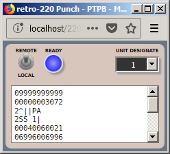
retro-220 Paper Tape Punch
The paper-tape punch is a simple unit that displays the words that have been punched in a scrolling window. The text in this window can be extracted and saved in the same way as for teletypes. Words are formatted as either numeric or alphanumeric depending on the value of the sign of the word being punched. The format of the text is compatible with the paper-tape reader, discussed next. See the Using the SPO, Teletype, and Paper Tape wiki page for details.

Paper Tape Reader


A 220 could optionally be configured with up to ten paper-tape readers. The readers operated at a switch-selectable speed of 500 or 1000 characters/second. Paper tape image files can be prepared with any text editor and loaded into the reader. Tape images saved from a paper-tape punch can also be loaded directly into the reader.

retro-220 Paper Tape Reader
A progress bar on the reader's window shows the relative amount of the tape image that has not yet been read. As the tape image is read, the words from the tape scroll horizontally across the bottom of the window. See the Using the SPO, Teletype, and Paper Tape wiki page for the format of paper-tape image files and details of the reader's operation.

The Cardatron


The Cardatron was a device that interfaced the 220 to IBM punched-card tabulating equipment. It was introduced with the ElectroData 205 shortly before Burroughs acquired ElectroData in 1956. It was then adapted to the 220 with very little change. For background on the Cardatron and how it worked, see the The Mighty CARDATRON and Using the retro-205 Cardatron blog posts.

For more details on the 220 Cardatron elements discussed below, see the Using the Cardatron wiki page and Section 6 in the Operational Characteristics manual.

Cardatron Control Unit


The Cardatron consisted of a Control Unit that interfaced to the processor, plus an Input or Output Unit that interfaced between the Control Unit and a specific IBM device. The Input/Output units could buffer a single card image, so some overlap in I/O operations was possible. Any combination of up to seven Input or Output units could be attached to the Control Unit.

In the emulator, the Cardatron Control Unit has a small window with a few indicator lamps. The lamps show status and unit selection, but you do not need to interact with this window when running the emulator. See the wiki page for an explanation of the lamps.

retro-220 Cardatron Control Unit

Cardatron Input Unit


The Input Unit interfaced card readers to the 220. Two types of readers could be used, the IBM Type 087/089 collator, operating at 240 cards/minute, and the Type 523 Summary Punch operating at 100 cards per minute. In the emulator, the reader operates at 240 cards/minute.

The Input Unit had a small drum that buffered one card image and stored up to five strings of digits known as "format bands." These strings described how to convert the punches in card columns to digits or characters in 220 memory words. A punch in a specified column on a card (often column 1 or 80) selected the band under which that card would be read and converted.

Each Input Unit displays as a separate window in the emulator. Card image files are ordinary text files and can be loaded into the reader much as decks of cards were loaded into the input hopper of a real reader. See the wiki page for an explanation of the controls and indicators on the reader window.

retro-220 Cardatron Input Unit / Card Reader

Cardatron Output Unit for Printer


There were two types of Output Unit, one supporting 80 columns for card punches and one supporting 120 columns for line printers. The 120-column unit was designed to connect to an IBM Type 407 tabulator operating at 150 lines/minute. This unit also had a small buffer drum that could buffer one line of print and store up to five format bands. The bands described how to converts words from the 220 memory to columns on a card or print line.

Each printer displays as a separate window in the emulator. Printed text can be extracted from its "paper" area and saved in the same manner as described for teletype units above. See the wiki page for an explanation of the controls and indicators on the printer window.

retro-220 Cardatron Output Unit / Printer

Cardatron Output Unit for Punch


The 80-column Output Unit was otherwise identical to the 120-column unit and was designed to connect to an IBM Type 523 Summary Punch operating at 100 cards/minute. The 523 could also be used as a card reader, but the same device could be be used in both ways. The punch window looks and operates similarly to the printer:

retro-220 Cardatron Output Unit / Punch

Magnetic Tape Storage


The 220 supported two types of magnetic tape devices. The Tape Storage Unit (TSU) was a traditional reel-to-reel device using 3/4-inch plastic tape wound on 3500-foot metal reels. Data was recorded digit-serial in two independent lanes on the tape. Recording was at 208.33 bits/inch with a tape speed of 120 inches/second. The emulator currently implements this device.

The second tape unit was the DataFile, a semi-random device consisting of 50 strips of tape accessed by a tape head assembly that traversed across the strips perpendicular to the tape motion. This device was also available on the 205. The retro-220 emulator does not presently support this device, but implementation in planned. For an introduction to the DataFile, see this 205 blog post.

The magnetic tape implementation on the 220 was both complex and sophisticated, and deserves a blog post on its own to describe its implementation and capabilities.

Tape Control Unit


Both the TSU and DataFile were controlled by a common Tape Control Unit (TCU). Up to ten tape drives, in any combination of TSUs and DataFiles, could be supported on a 220 system.

In the emulator, this unit has a window that displays its major flip-flops and two main registers. You do not normally need to interact with the TCU when operating the emulator, but it shows information that may be useful in diagnosing tape errors. The TCU may need to be cleared to recover from some types of tape errors. The CLEAR button on this unit has the same function as the TCU CLEAR switch on the Control Console.

retro-220 Magnetic Tape Control Unit (TCU)

Tape Storage Unit


In the emulator, each TSU has a window that displays controls and indicators used to operate the unit and monitor its state.

retro-220 Magnetic Tape Storage Unit (TSU)
When a tape image is loaded in the unit, a small reel icon will appear in the upper-right of the window. This icon will spin in response to tape commands addressing the unit. Annunciators will appear below this reel to indicate certain conditions (e.g., REWINDING, AT BOT).

The blue lamps across the top of the window indicate the status of the drive. The most important of these are the NOT READY, TRANSPORT POWER ON (unit is on line), and TRANSPORT POWER OFF (unit is off line).

The red and black buttons below the lamps control the unit. LOAD and UNLOAD initiate the loading and unloading of tape images in the unit. REWIND will rewind the tape to its load point (BOT, Beginning of Tape) if the unit is off line. ON and ST'DBY switch the unit between on-line and off-line status. RWLR releases a "rewind lockout" condition that is imposed by a variant of the processor's tape rewind instruction. WRITE and NOT WRITE control write protection for a mounted tape image.

The UNIT DESIGNATE pull-down list determines the logical unit number to which the unit will respond. This is the unit number specified in tape instructions. Not more than one TSU should be on-line at the same time with the same unit number. If more than one TSU is on line with the same number, all such TSUs will appear to the processor as not ready.

At the bottom of the window is a meter bar that, when a tape image is loaded into the unit, shows the relative amount of tape left on the reel. The bar will move to the left as tape is read in a forward direction. Above the bar is the name of tape image currently loaded into the unit.

Tape images are ordinary comma-delimited (CSV) text files. They can be prepared manually using a text editor or spreadsheet program. When unloading a tape image, if the image has been updated while it was loaded, the emulator will pop up an alert offering to save the updated image. Since browsers cannot write directly to your workstation's file system, the updated image will be formatted in a temporary window, from which you can copy or save it. Tape image files are copied into the emulator's memory when they are loaded, and are operated on in memory. The file from which the image is loaded is not updated by the emulator, but you can save the text of an image back to the same file name to obtain the same effect.

This brief overview of TSU operation and behavior is intended to give you an introduction to the use of magnetic tape on the 220. For more detailed instructions on loading and unloading tape images and on the format of tape image files, see the Using Magnetic Tape page in the wiki.


Running the Pre-Loaded Programs


The preceding introduction should give you enough information to load the 220 emulator into your browser and operate its controls. Just to give the emulator something to do out of the box (i.e., make the lights blink), the emulated memory is pre-loaded with a few small demonstration programs. These are all self-contained and use only the SPO teletype for output. The starting address for each of these programs is:

  * 0080 -- a simple counter program that increments the A register as fast as possible. Each iteration should take 0.310ms, or about 3226 iterations/second.
  * 0090 -- the classic Hello World program, which with default Console unit designations will write to the SPO, and then halt.
  * 0100 -- a program that computes square roots using integer arithmetic, printing the argument and root values to the SPO. This program uses the decimal-point insertion feature of the SPO.
  * 0200 -- the same square root program as at 0100 modified to use floating point arithmetic. Floating point numbers are represented as seemmmmmmmm, where s is the sign digit, ee is the exponent biased by 50, and mmmmmmmm is the eight-digit mantissa with the decimal point to the left of the first digit. The number 2.23602 (or 0.223602E+01) is therefore represented in the 220 as +5122360200. The program also uses the decimal-point insertion feature, so this value will print on the SPO as 51.2360200.
  * 0300 -- a program that prints the first 800 digits of Pi, adapted from a C program by Dik Winter of CWI in Amsterdam. The results are printed on the SPO in four-digit groups. It takes about 25 seconds for the first group to print. The remaining groups will come out progressively faster. The program takes about 40 minutes to run to completion. The B register counts down as a four-digit group is generated; the group will print when B reaches zero.

There are two methods you can use to run these programs from the Control Console.

Method 1: Finger-boning the Console lamps:
  1. Click the CLEAR switch on the Console.
  2. Enter the address of the routine in the lamps of the P register. All digits are in BCD, with the low-order bit of the digits in the bottom row of the register lamps.
  3. Make sure the FETCH lamp is lit. Click it if necessary. This will cause the processor to start by fetching the first instruction from the address in P.
  4. Click the START switch to begin execution.
The following screen shot shows the panel as it should be set to run the Hello World program at address 0090:

Setting a Program Starting Address

Method 2: Using the Console Keyboard:
  1. Click the CLEAR switch.
  2. Click the KEYBOARD switch. The keyboard window should appear in the lower-right corner of the screen.
  3. Enter 30xxxx by either clicking the numeric digits of the Console keyboard or typing on your workstation keyboard. "xxxx" is the address of the program you wish to run. This is a Branch Unconditional (BUN) instruction. You will see the digits shift into the D register.
  4. Click the C key on the Console keyboard (or type "c" on your workstation keyboard). This will transfer the contents of D to the C register.
  5. Click the EXECUTE lamp to place the Processor in the Execute Phase. This will cause it to start with the instruction in the C register.
  6. Click the START switch on the Console to begin execution.
The programs at locations 0080, 0100, and 0200 will run continuously until they are halted by clicking the STOP or CLEAR switches. The programs at 0090 and 0300 will run to completion and then halt. The RUN lamp will extinguish. These programs can be stopped manually at any time.

You can also single-step the programs to see individual instructions execute. Simply click the STEP switch on the Console or they keyboard. The Processor must be halted (RUN lamp is off) for the STEP switch to be active. Note that it takes two steps to execute one instruction -- one step for the Fetch Phase and one for the Execute Phase. The FETCH and EXECUTE lamps indicate which phase will be performed next when STEP is clicked.


Conclusion


This concludes the overview of the retro-220 emulator in its current state of development. The DataFile magnetic tape and High Speed Printer devices will be implemented at some point in the future, but there is presently no schedule for their development.

The next post will discuss the Burroughs Algebraic Compiler (BALGOL) and the process used to recover it from a listing and get it running again.