This is Paul Kimpel with another post on Tom's 205 and 220 blog.. That prior post laid the groundwork for this one -- to introduce the emulator I've developed for the 220. This post will present the features of that emulator, discuss its current state of development, describe how you can use it, and point you to the documentation and relevant reference materials.
As with my earlier retro-205 emulator for the 205 and retro-b5500 emulator for the Burroughs B5500, the retro-220 emulator is written in Javascript and runs in a standard web browser. Multiple windows on the screen are used to display the panels and peripheral devices of the system.
For the impatient who don't want to read through the following, the source code and resource files for the emulator are maintained as an open-source project at https://github.com/pkimpel/retro-220/. You can run the emulator from a hosting site I have set up, or you can download the files from the project's Git repository and set them up on your own web server. See the section Using the Emulator, below, for details on how to do this. Additional set-up and operating instructions can be found in the project wiki.
Choosing to Emulate the 220
While building an emulator for the 220 is a logical sequel to my earlier retro-205 emulator for the 205, this emulator is the fulfillment of an idea I've been carrying for almost 30 years. In August 1991, I visited the original Computer Museum in Boston, Massachusetts. After spending several satisfying hours viewing the exhibits, I was browsing in the museum's bookstore, and found a section that had old computer manuals. These were probably documents that had been donated to the museum, but were duplicates of ones they already had, so they were offering them for sale.
I have spent much of my career working with Burroughs systems and their Unisys successors. I had been disappointed to see nothing from that line in the museum's exhibits, but there in the bookstore I saw a manual titled The Operational Characteristics of the Datatron 220 Electronic Data-Processing System, Preliminary Edition from 1957. I was delighted to find this and bought it on the spot. It was only $6.00.
 |
| The Manual That Started It All |
Sometimes an early enthusiasm like this runs aground on the reality of what it takes to bring an idea to fruition, but sometimes that reality turns out to be way more interesting than the original enthusiasm, and that has certainly been the case here.
So that, dear reader, is how I became interested in emulating old computers -- to make the lights blink.
I also had a friend, the late Al Collins, who had worked for ElectroData and Burroughs in Pasadena during the 1950s and early 1960s. Al loved to tell stories. He had quite a few about the 205, the 220, and the early days of the B5000. It was also from Al that I originally learned of the BALGOL compiler for the 220. Al had a listing of the compiler, which his family and I were unable to find after he passed away. I found one on bitsavers.org, though, along with additional 220 reference materials, and that reignited the idea of some day not only emulating the 220, but also restoring that compiler and getting it to run again. Then I found a later and more complete listing that Professor Donald Knuth had donated to the Computer History Museum.
With that, I appeared to have everything I needed to build an emulator for the 220 and restore a significant piece of software for it. Thus the goals of this project became similar to those for the retro-205 emulator:
- Design and build the emulator so that it will run in a modern, standards-compliant web browser.
- Emulate the 220 processor, memory, and input/output devices as faithfully as is practical within he constraints imposed by a browser environment. In particular, the emulator should run programs exactly as a 220 would have run them.
- Execute 220 programs as closely as possible to the actual speed of a real 220. Emulation at speed is something I have been fairly successful at achieving with the 205 and B5500 emulators, and I think it is an important component for faithful emulation of any computer system, but for especially older ones that are so much slower than current systems.
- Provide as faithful a user experience as is practical within the constraints of a web-browser environment. The goal is for you to be able to use the emulator the same way you would have used a 220, with allowances for the fact that the emulator is not a physical piece of hardware. The user interface should be at least evocative of the physical machine, though, especially with respect to the control panels and I/O devices.
- Reconstruct and make operational the BALGOL compiler from the scanned listings on the Computer History Museum's web site.
Current Development Status
The BALGOL compiler and library comprises over 10,700 lines of assembler coding, so I started transcribing that first, in early November 2016. Design and coding of the emulator began in late January 2017. Transcription of the BALGOL listings was completed in early February 2017 and an initial proofing pass by early April. Implementation of the emulator, except for magnetic tape devices, was essentially complete by the end of May 2017.
Magnetic tape is required for the BALGOL compiler, but magnetic tape on the 220 was a complex device, and proved to be quite a challenge to implement. The project stalled for several months in the face of that challenge, and I did not finally have it working until mid-November 2017, almost a year after the project began.
Work to date since then has mostly involved assembling the compiler pieces into a running program and testing the compiler with a few sample programs. I will devote future blog posts to a detailed description of the recovery and reconstruction of the compiler and the sample programs we presently have working. The materials for these are available now, however, on the project's GitHub repository.
At this point, the 220 emulator is complete except for the DataFile, a semi-random tape mechanism similar to the one available on the 205, and the High Speed Printer (HSP), an early drum printer. All instructions for the 220 processor, except those for the HSP, are presently implemented, including those for floating-point arithmetic.
The emulator is written entirely in Javascript, with HTML and CSS used to lay out the user interface. It requires a fairly modern web browser in order to run, as it employs a number of features from the on-going HTML5 standardization effort. The emulator works and has been tested with reasonably-recent versions of Google Chrome, Mozilla Firefox, and Apple Safari for Mac OS. The emulator will not work with tablet devices, as tablets do not support multiple windows on the screen.
Two people have given me a great deal of advice and assistance on this project, and have helped make it a success. Tom Sawyer, as always, has continued his strong support for my efforts, and uncovered much interesting and useful information during his research at the Charles Babbage Institute in Minneapolis. Through Tom, I met Michael Mahon on line. Michael used a 220 during his graduate studies at Cal Tech in the mid-1960s. His memories of actually using a system have been invaluable. Michael has written his own emulator for the 220 -- that runs on an Apple II! He also wrote a paper-tape based assembler for the 220, SNAP, while at Cal Tech, and has generously made the source code for that program available to this project.
Using the Emulator
As mentioned above, the emulator requires a modern browser, with Firefox and Chrome being the two I have used the most. You will also need a reasonably powerful workstation. Emulation of the 220 instructions requires almost nothing, but update of the panels and I/O device windows can be very graphics-intensive, and requires a fair amount of horsepower. My five-year old Dell PC with a 3GHz quad-core Pentium i3 processor handles the emulator adequately. It will also help if you have a big monitor, as the windows for the control console and I/O devices tend to overlap each other.
The emulator must be served to your browser from a web server over HTTP. You will not be able to download the emulator files to your workstation and run them directly from your local file system. That is a limitation with the way that browsers work, not with the emulator. Of course, there's no reason you can't run a web server on your workstation and serve the emulator files from there. Regardless, once the emulator is loaded into your workstation, it runs entirely locally, and needs no further access to the web server.
Setting Up the Emulator
The easiest way to get started with the emulator is to use the hosting site, where I have set up the emulator files. Feel free to use it:
If you would prefer to run the emulator from another web server, download the files from the Git repository on the project site. You can download a zip file of the latest version of the emulator source code by clicking the Download ZIP button on the project's home page:
Alternatively, you can clone the project from the repository using the following Git command:
git clone https://github.com/pkimpel/retro-220 retro-220
Although the GitHub project site uses a Git source code repository, GitHub also allows you to access the repository using Subversion clients. A read-only checkout of the emulator files can be performed using a Subversion command similar to this:
svn checkout https://github.com/pkimpel/retro-220/trunk retro-220
You will need at least the emulator/, webUI/, and webUI/resources/ directories from the repository. The emulator/ and webUI/ directories must be rooted in the same virtual directory on your web server. You may also wish to download/check out the software/ directory, as it contains a number of 220 programs, but that directory is not required to run the emulator.
The emulator will open a number of sub-windows when it initializes. Most browsers will consider these windows to be "pop-ups," so if you are using a pop-up blocker, you should disable it before starting the emulator. Most pop-up blockers will allow you to disable blocking for specific web sites, however, which will allow you to run the emulator without having to forgo protection from pop-ups for all sites. Modern browsers enable a pop-up blocker by default, and many browser toolbar plug-ins implement additional ones. All of them will need to be disabled for the emulator site.
More information on system requirements, setting up the emulator, and using a local web server is available on the Getting Started wiki page.
The Emulator Home Page
When you first load the emulator, it initializes with a default configuration, which is adequate in most cases to get started using it. Once it loads into your browser, it's ready to run. The hosting-site URL above references the emulator's home page, which looks like this:
 |
| retro-220 Emulator Home Page |
The current version of the emulator is shown in the upper-right corner of the page. There are links below the horizontal bar to the open-source project site and to this blog. The picture is from Michigan National Bank in Lansing, Michigan, ca. 1960. In the background are tape drives and a portion of the system cabinetry. In the foreground is the system's Control Console.
Below the picture are two large blue buttons. The Configure System button can be used to modify the system configuration. It is active only when the emulator is in a "powered-off" state. The emulator is initially configured for 5000 words of memory, one teletype printer (the "SPO"), one paper-tape reader, no paper-tape punch, one card reader, one line printer, one card punch, and two magnetic tape drives. See the Configuring the 220 Emulator wiki page for instructions on modifying the configuration.
To start the emulator, click the Start the Emulator button below the picture. Additional windows will open for the Control Console panel and the I/O devices. The blue button will become disabled after it is clicked, and will remain so until the emulator is powered off from the Control Console as discussed below. While the emulator is running, the home page is not needed, but do not to close or minimize it -- just leave it in the background.
Also note that some browsers, particularly Firefox, will slow execution of scripts for a web page if that page is in a tab other than the currently-active one of a window. In the case of the emulator, this means that if the home page is in a non-active tab, the emulator will likely run very slowly. If you need to use the browser for another purpose while the emulator is running, leave the emulator's home page in the active tab of its window and open another window for the other purpose.
The Control Console
The 220 had a large and impressive console built into a desk. The central panel of the console was used to operate the system. There were two additional panels on either side of the main one that were normally concealed by snap-off covers. These were used mainly by the field engineers for system diagnosis and maintenance. The emulator does not presently implement those additional panels. The main panel looks like this in a browser:
 |
| retro-220 Control Console |
Register Displays
The first two rows on this panel show the main registers for the system. The 220 was a decimal system that used BCD (binary-coded decimal) encoding, so the registers are arranged as groups of columns, with each column holding one four-bit digit. The bits in each column have values 8-4-2-1 from top to bottom. Thus a digit 7 has the bottom three bits set; a digit 9 has the top and bottom bits set. Digit values 10-15 are termed "Forbidden Combinations" and will cause the system to halt with a Digit Check alarm.
The first row has registers A (the accumulator), R (the accumulator extension), and D (a register through which data entered and exited the processor). The second row has B (the index register), P (the program address counter), C (the command, or current-instruction register), E (the memory address register), and S (the stop or breakpoint-address register, used in debugging programs). The purpose of these registers is described in Section 2 of the Operational Characteristics manual available on bitsavers.org.
On a real 220, there were small white rectangular buttons below each lamp of a register that, when pressed, would set that bit to 1. To reset a bit, you would hold down the large white rectangular button on the left side of the register while simultaneously pressing the small white button for that bit. This is awkward to do with most pointing devices, so in the emulator the large left-hand button is inactive, and each click of the lamp or the white button below it toggles the current state of that bit. Clicking the large white rectangular button on the right side of a register clears that register.
Indicator Lamps
In the row below the registers are three groups of colored lamps. The group on the left consists of red lamps that light when an error or alarm condition is sensed by the system. These conditions cause the system to halt. Most of these lamps are also buttons, which can be clicked to reset the corresponding alarm condition. See Section 3 in the Operating Procedures manual for information on the conditions each of these lamps represents.
The middle group consists of three blue lamps that indicate the processor's current state.
- The RUN lamp is lit when the processor is executing instructions in continuous mode.
- The FETCH and EXECUTE lamps indicate the current phase in which the processor is operating. 220 instructions are executed in two steps:
- During the Fetch phase, the next instruction is loaded into the C register from memory at the address in the P register, and then P increments by one. If the low-order bit of the sign digit in the instruction word is 1, the value in the B register is added to the operand address in the low-order four digits of the C register.
- Once the C register is loaded, the phase switches to Execute and the instruction is executed. The phase then switches back to Fetch and the process repeats. The two lamps indicate the phase the processor will enter next.
- OVERFLOW indicates that arithmetic overflow has occurred during the execution of an instruction. It is sensed and reset by the Branch Overflow instruction.
- REPEAT is set by the Decrease Field Location and Decrease Field Location Load B instructions that decrement a field in a word. It is sensed by the Branch Repeat instruction. It is used to control the execution of loops.
- The LOW, EQUAL, HIGH lamps indicate the last result of the Compare Field A/R instructions and are sensed by the Branch Low/High/Equal/Unequal instructions.
Control Switches
The row below the lamps contains groups of switches. These were in the form of large "organ switches," similar to the paddle switches that control stops on an organ. They were made of translucent plastic, and came in two types: momentary switches that acted like a button, and latched switches that would maintain their position. The latched switches were lit when in the "on" (down) position.
The group of switches on the left consist of ten Program Control Switches that are of the latched type. The settings of these switches can be sensed by the Branch Control Switch instruction, and are used to set options for, or to communicate dynamically with, a program.
The group of four momentary switches in the middle control the system's operation:
- STOP halts the processor, preserving its current state. Execution can be continued using the RUN or STEP switches.
- RUN starts the processor in continuous execution. This switch is enabled only when the processor is halted and the blue RUN lamp is off.
- STEP starts the processor, but only for the next Fetch or Execute phase. At the end of that phase, the processor halts. Thus, this switch needs to be pressed twice to completely execute one instruction. This switch is also enabled only when the processor is halted and the blue RUN lamp is off.
- CLEAR clears all registers and flip-flops in the processor. If the processor is running when this switch is pressed, it halts.
- KEYBOARD is a momentary switch that enables the decimal keyboard, as described below. This switch is enabled only when the processor is halted and the blue RUN lamp is off.
- "S" ON is a latched switch that enables the S register. This register holds a memory address that, when accessed in the manner indicated by the next three switches, will cause the processor to halt. When this switch is off, the value in the S register and the other three switches are ignored.
- UNITS is a latched switch that, when on, will cause only the low-order digit of the S register to be compared in detecting a stop address.
- "S" TO P is a latched switch that indicates the processor is to halt at the end of the Fetch phase when the P register matches the S register. P increments during Fetch, so the processor will halt with P one greater than S.
- "S" TO C is a latched switch that indicates the processor is to halt at the end of the Execute phase when the low-order four digits of the C register (the operand address) matches the S register.
- RESET/TRANSFER is a momentary switch that, when clicked, will cause the contents of the P register and the low-order four digits of the C register to be stored in memory location 0000. The processor will then branch to the instruction at memory address 0001. This switch worked somewhat like an interrupt, and could be used to recover control of the system after certain peripheral errors that do not allow the Execute phase of an instruction to complete.
- TCU CLEAR is a momentary switch that, when clicked, clears the Magnetic Tape Control Unit. This was used to recover from certain magnetic tape errors. It performs the same function as the CLEAR button on the TCU panel.
Interval Timer
In the center at the bottom of the panel is the interval timer. On a real 220, this was a separate mechanical timer that was attached to the console by a cable and usually sat on the console desk. This timer runs whenever the processor is executing instructions and the blue RUN lamp is lit. It records time in seconds and tenths, counting up to 9999.9 before rolling over to zero. The timer can be reset to zero at any time by clicking the black ZERO TIMER button on its left.
Power Off Button
To the right of the timer is a red button captioned POWER OFF. This button must be double-clicked to activate it. Doing so will stop the processor if it is running, and close the Control Console and all peripheral device windows, leaving open only the window for the emulator's home page. The contents of the 220 memory and peripheral devices will be lost. Make sure that you capture any output you wish to keep from the peripheral devices before powering off the emulator.
Memory Dump Feature
The retro-220 emulator supports a diagnostic feature on the console. If you click the circular "B" logo at the top of the panel (affectionately known within Burroughs as "the Meatball"), the emulator will open a temporary window on your screen and format the processor's current register settings and all of memory to it. From this window you can view the dump, or copy/save the text to another program or a file. You can generate these dumps as often as you like, even while the system is running. Each dump will open in a separate temporary window. When you are finished with a dump, simply close its window.
More information on the Control Console is available in the Using the Control Console wiki page and in Section 3 of the Handbook of Operating Procedures for the Burroughs 220.
The Console Keyboard
The 220 Control Console has a decimal keyboard. This was another module connected to the console by a cable, and usually sat on the console desk. The emulator implements this keyboard as a separate window, but that window is not displayed by default. To open the window and enable the keyboard, click the KEYBOARD momentary switch on the console. This switch is enabled only when the processor is halted and the blue RUN lamp is not lit.
 |
| 220 Control Console Decimal Keyboard |
Keying the decimal buttons causes those digits to enter the processor's D register from the right, shifting the other digits in the register to the left in the process. The high-order digit in the sign position of the register shifts off and is lost. If you make a mistake, you can clear the D register and start over, or simply keep keying digits, possibly with some leading zeroes to clear out digits in the register you don't want.
The other buttons on the console keyboard function as follows. The characters in brackets indicate the equivalent keys you can press on your workstation keyboard:
- C [C, c] -- transfers the contents of the low-order ten digits of the D register to the C register. If the low order bit of the sign digit in the D register is set, B-register modification of the operand address in the C register occurs. The D register is unaffected.
- E [E, e] -- transfers the low-order four digits of the D register to the E register and clears the D register. This establishes the memory address used by the next two buttons.
- EXAM [X, x] -- loads the word from memory at the address in E to the D register. The E register counts up by one.
- ENT [Enter, Return] -- stores the contents of the D register to the memory address in the E register. The E register counts up by one.
- STEP [S, s] -- acts the same as the STEP switch on the Control Console.
- ADD [+] -- algebraically adds the value of the D register to the A register and then starts the processor as if RUN had been clicked. This feature is designed to be used with the Keyboard Add instruction. When this instruction is executed, the D register is cleared, the processor halts, and the keyboard is enabled automatically. Once the ADD key is pressed, D is added to A and the processor resumes execution.
Input/Output Devices
The 220 supported a number of contemporary peripheral devices for input and output of data. At present, the emulator supports teletype printers, paper tape readers and punches, the Cardatron interface for IBM punched-card equipment, and reel-to-reel magnetic tape drives. The emulator does not at present support the DataFile magnetic tape unit nor the High Speed Printer.
Teletypes and the SPO
A 220 system could support up to ten teletype printers. Every system had an additional teletype known as the Supervisory Printer, or SPO (pronounced "spOH"), which was addressed with a different instruction than the other teletypes. All printers were identical Teletype Model 28 units that printed at 10 characters/second, although Burroughs later introduced some high-speed printers that were plug-compatible with the Model 28. Any teletype could be designated as the SPO; a paper-tape punch could also be designated as the SPO.
Each teletype device is displayed as a separate window in the emulator.
 |
| retro-220 SPO/Teletype Printer Window |
Paper Tape Punch
A 220 could optionally be configured with up to ten paper-tape punches. The punch operated at 60 characters/second, using a seven-level code compatible with the IBM 046 Tape to Card Converter. Teletypes and paper-tape punches share the same set of device addresses, so a system could support any combination of the two devices up to a total of ten units.
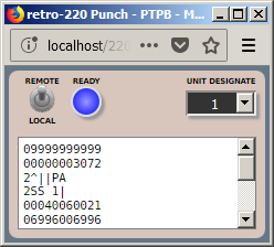 |
| retro-220 Paper Tape Punch |
Paper Tape Reader
A 220 could optionally be configured with up to ten paper-tape readers. The readers operated at a switch-selectable speed of 500 or 1000 characters/second. Paper tape image files can be prepared with any text editor and loaded into the reader. Tape images saved from a paper-tape punch can also be loaded directly into the reader.
 |
| retro-220 Paper Tape Reader |
The Cardatron
The Cardatron was a device that interfaced the 220 to IBM punched-card tabulating equipment. It was introduced with the ElectroData 205 shortly before Burroughs acquired ElectroData in 1956. It was then adapted to the 220 with very little change. For background on the Cardatron and how it worked, see the The Mighty CARDATRON and Using the retro-205 Cardatron blog posts.
For more details on the 220 Cardatron elements discussed below, see the Using the Cardatron wiki page and Section 6 in the Operational Characteristics manual.
Cardatron Control Unit
The Cardatron consisted of a Control Unit that interfaced to the processor, plus an Input or Output Unit that interfaced between the Control Unit and a specific IBM device. The Input/Output units could buffer a single card image, so some overlap in I/O operations was possible. Any combination of up to seven Input or Output units could be attached to the Control Unit.
In the emulator, the Cardatron Control Unit has a small window with a few indicator lamps. The lamps show status and unit selection, but you do not need to interact with this window when running the emulator. See the wiki page for an explanation of the lamps.
 |
| retro-220 Cardatron Control Unit |
Cardatron Input Unit
The Input Unit interfaced card readers to the 220. Two types of readers could be used, the IBM Type 087/089 collator, operating at 240 cards/minute, and the Type 523 Summary Punch operating at 100 cards per minute. In the emulator, the reader operates at 240 cards/minute.
The Input Unit had a small drum that buffered one card image and stored up to five strings of digits known as "format bands." These strings described how to convert the punches in card columns to digits or characters in 220 memory words. A punch in a specified column on a card (often column 1 or 80) selected the band under which that card would be read and converted.
Each Input Unit displays as a separate window in the emulator. Card image files are ordinary text files and can be loaded into the reader much as decks of cards were loaded into the input hopper of a real reader. See the wiki page for an explanation of the controls and indicators on the reader window.
 |
| retro-220 Cardatron Input Unit / Card Reader |
Cardatron Output Unit for Printer
There were two types of Output Unit, one supporting 80 columns for card punches and one supporting 120 columns for line printers. The 120-column unit was designed to connect to an IBM Type 407 tabulator operating at 150 lines/minute. This unit also had a small buffer drum that could buffer one line of print and store up to five format bands. The bands described how to converts words from the 220 memory to columns on a card or print line.
Each printer displays as a separate window in the emulator. Printed text can be extracted from its "paper" area and saved in the same manner as described for teletype units above. See the wiki page for an explanation of the controls and indicators on the printer window.
 |
| retro-220 Cardatron Output Unit / Printer |
Cardatron Output Unit for Punch
The 80-column Output Unit was otherwise identical to the 120-column unit and was designed to connect to an IBM Type 523 Summary Punch operating at 100 cards/minute. The 523 could also be used as a card reader, but the same device could be be used in both ways. The punch window looks and operates similarly to the printer:
 |
| retro-220 Cardatron Output Unit / Punch |
Magnetic Tape Storage
The 220 supported two types of magnetic tape devices. The Tape Storage Unit (TSU) was a traditional reel-to-reel device using 3/4-inch plastic tape wound on 3500-foot metal reels. Data was recorded digit-serial in two independent lanes on the tape. Recording was at 208.33 bits/inch with a tape speed of 120 inches/second. The emulator currently implements this device.
The second tape unit was the DataFile, a semi-random device consisting of 50 strips of tape accessed by a tape head assembly that traversed across the strips perpendicular to the tape motion. This device was also available on the 205. The retro-220 emulator does not presently support this device, but implementation in planned. For an introduction to the DataFile, see this 205 blog post.
The magnetic tape implementation on the 220 was both complex and sophisticated, and deserves a blog post on its own to describe its implementation and capabilities.
Tape Control Unit
Both the TSU and DataFile were controlled by a common Tape Control Unit (TCU). Up to ten tape drives, in any combination of TSUs and DataFiles, could be supported on a 220 system.
In the emulator, this unit has a window that displays its major flip-flops and two main registers. You do not normally need to interact with the TCU when operating the emulator, but it shows information that may be useful in diagnosing tape errors. The TCU may need to be cleared to recover from some types of tape errors. The CLEAR button on this unit has the same function as the TCU CLEAR switch on the Control Console.
 |
| retro-220 Magnetic Tape Control Unit (TCU) |
Tape Storage Unit
In the emulator, each TSU has a window that displays controls and indicators used to operate the unit and monitor its state.
 |
| retro-220 Magnetic Tape Storage Unit (TSU) |
The blue lamps across the top of the window indicate the status of the drive. The most important of these are the NOT READY, TRANSPORT POWER ON (unit is on line), and TRANSPORT POWER OFF (unit is off line).
The red and black buttons below the lamps control the unit. LOAD and UNLOAD initiate the loading and unloading of tape images in the unit. REWIND will rewind the tape to its load point (BOT, Beginning of Tape) if the unit is off line. ON and ST'DBY switch the unit between on-line and off-line status. RWLR releases a "rewind lockout" condition that is imposed by a variant of the processor's tape rewind instruction. WRITE and NOT WRITE control write protection for a mounted tape image.
The UNIT DESIGNATE pull-down list determines the logical unit number to which the unit will respond. This is the unit number specified in tape instructions. Not more than one TSU should be on-line at the same time with the same unit number. If more than one TSU is on line with the same number, all such TSUs will appear to the processor as not ready.
At the bottom of the window is a meter bar that, when a tape image is loaded into the unit, shows the relative amount of tape left on the reel. The bar will move to the left as tape is read in a forward direction. Above the bar is the name of tape image currently loaded into the unit.
Tape images are ordinary comma-delimited (CSV) text files. They can be prepared manually using a text editor or spreadsheet program. When unloading a tape image, if the image has been updated while it was loaded, the emulator will pop up an alert offering to save the updated image. Since browsers cannot write directly to your workstation's file system, the updated image will be formatted in a temporary window, from which you can copy or save it. Tape image files are copied into the emulator's memory when they are loaded, and are operated on in memory. The file from which the image is loaded is not updated by the emulator, but you can save the text of an image back to the same file name to obtain the same effect.
This brief overview of TSU operation and behavior is intended to give you an introduction to the use of magnetic tape on the 220. For more detailed instructions on loading and unloading tape images and on the format of tape image files, see the Using Magnetic Tape page in the wiki.
Running the Pre-Loaded Programs
The preceding introduction should give you enough information to load the 220 emulator into your browser and operate its controls. Just to give the emulator something to do out of the box (i.e., make the lights blink), the emulated memory is pre-loaded with a few small demonstration programs. These are all self-contained and use only the SPO teletype for output. The starting address for each of these programs is:
* 0080 -- a simple counter program that increments the A register as fast as possible. Each iteration should take 0.310ms, or about 3226 iterations/second.
* 0090 -- the classic Hello World program, which with default Console unit designations will write to the SPO, and then halt.
* 0100 -- a program that computes square roots using integer arithmetic, printing the argument and root values to the SPO. This program uses the decimal-point insertion feature of the SPO.
* 0200 -- the same square root program as at 0100 modified to use floating point arithmetic. Floating point numbers are represented as seemmmmmmmm, where s is the sign digit, ee is the exponent biased by 50, and mmmmmmmm is the eight-digit mantissa with the decimal point to the left of the first digit. The number 2.23602 (or 0.223602E+01) is therefore represented in the 220 as +5122360200. The program also uses the decimal-point insertion feature, so this value will print on the SPO as 51.2360200.
* 0300 -- a program that prints the first 800 digits of Pi, adapted from a C program by Dik Winter of CWI in Amsterdam. The results are printed on the SPO in four-digit groups. It takes about 25 seconds for the first group to print. The remaining groups will come out progressively faster. The program takes about 40 minutes to run to completion. The B register counts down as a four-digit group is generated; the group will print when B reaches zero.
There are two methods you can use to run these programs from the Control Console.
Method 1: Finger-boning the Console lamps:
- Click the CLEAR switch on the Console.
- Enter the address of the routine in the lamps of the P register. All digits are in BCD, with the low-order bit of the digits in the bottom row of the register lamps.
- Make sure the FETCH lamp is lit. Click it if necessary. This will cause the processor to start by fetching the first instruction from the address in P.
- Click the START switch to begin execution.
 |
| Setting a Program Starting Address |
Method 2: Using the Console Keyboard:
- Click the CLEAR switch.
- Click the KEYBOARD switch. The keyboard window should appear in the lower-right corner of the screen.
- Enter 30xxxx by either clicking the numeric digits of the Console keyboard or typing on your workstation keyboard. "xxxx" is the address of the program you wish to run. This is a Branch Unconditional (BUN) instruction. You will see the digits shift into the D register.
- Click the C key on the Console keyboard (or type "c" on your workstation keyboard). This will transfer the contents of D to the C register.
- Click the EXECUTE lamp to place the Processor in the Execute Phase. This will cause it to start with the instruction in the C register.
- Click the START switch on the Console to begin execution.
You can also single-step the programs to see individual instructions execute. Simply click the STEP switch on the Console or they keyboard. The Processor must be halted (RUN lamp is off) for the STEP switch to be active. Note that it takes two steps to execute one instruction -- one step for the Fetch Phase and one for the Execute Phase. The FETCH and EXECUTE lamps indicate which phase will be performed next when STEP is clicked.
Conclusion
This concludes the overview of the retro-220 emulator in its current state of development. The DataFile magnetic tape and High Speed Printer devices will be implemented at some point in the future, but there is presently no schedule for their development.
The next post will discuss the Burroughs Algebraic Compiler (BALGOL) and the process used to recover it from a listing and get it running again.